Student Handbook |
LAND NAVIGATION
FMST 0205
03 Nov 99
TERMINAL
LEARNING OBJECTIVES
1.
Given a combat environment (day and night), and individual combat
equipment, navigate terrain using a map and compass per the reference.
(FMST.02.05)
ENABLING
LEARNING OBJECTIVES
1.
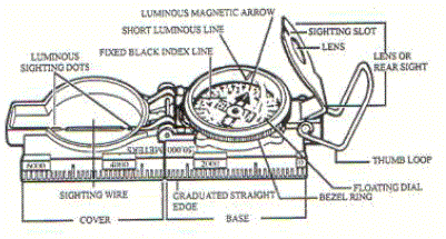
Without the aid of reference materials, identify the nomenclature on the
compass, per the student handout. (FMST.02.05a)
2.
Without the aid of reference materials and given a map and compass,
select the two methods of orienting the map, per the student handout.
(FMST.02.05b)
3.
Without the aid of reference materials, identify the five basic colors
found on map, per the student handout. (FMST.02.05c)
4.
With the aid of a military map, locate a point on the map from a six
digit grid coordinate, per the reference. (FMST.02.05d)
5.
Without the aid of reference materials, select the two methods to hold
the compass, per the student handout. (FMST.02.05e)
6.
Given a compass and map, while on the land navigation course, locate a
point using the six digit grid coordinate, and determine a route on the course,
per the student handout. (FMST.02.05f)
OUTLINE
A.
Lensatic
Compass DESCRIPTION. The
primary instrument used to determine and maintain direction during land
navigation is the lensatic compass. This
compass provides the most reliable means of accurately maintaining direction
while navigating from one point to another.
The name “lensatic compass” derives from the magnifying lens which is
mounted in the eyepiece. There are
three major parts to the compass: Cover,
Base, and Lens
1.
Nomenclature
a.
Graduated Straight Edge.
Formed by the case and cover when the compass is fully opened.
When used on a 1:50,000 map, each line of the scale represents 200 meters
of ground distance.
b.
Thumb Loop.
Aids in keeping the compass level while shooting an azimuth.
c.
Lens. Used to read the numbers on the floating dial.
d.
Sighting Slot.
Functions the same as the rear sight of a rifle.
e.
Sighting Wire.
Used in a similar fashion as the front sight of a rifle when shooting an
azimuth.
f.
Luminous Sighting Dots.
Used in place of the sighting wire at night.
g.
North Seeking Arrow.
Points towards magnetic north. This
is a luminous arrow.
h.
Bezel Ring.
Enables you to follow an azimuth at night.
As the bezel ring is turned, the tip of a detent spring moves from notch
to notch along the ring. Each click
is equal to a three degree change in direction.
i.
Index Line.
The azimuth you read will be directly under the index line.
j.
Short Luminous Line.
Used in conjunction with the index line and luminous arrow to follow an
azimuth.
k. Floating Dial. Contains the degrees and mils. Used for the direction in which you are pointing your compass.

B. Compass Precautions. Certain precautions regarding the care and use of a magnetic compass are important because they ensure, within reason, that a compass will work when needed.
1. The dial has a delicate balance and a rough shock could damage it.
2. WHEN NOT IN USE, CLOSE AND PUT THE COMPASS AWAY TO PROTECT IT
3. Metal and electrical wires have an adverse effect on the operation of the lensatic compass. Recommended safe distances from certain objects are:
a. High-tension power lines.....…. 55 meters
b. Field gun, truck, or tank....…... 10 meters
c. Barbed wire, telephone wires... 10 meters
d. Machinegun...................……... 2 meters
e. Rifle........................…………… 0.5 meters
4. Nonmagnetic metals and alloys do not effect compass readings.
C. Methods to hold Compass. There are two methods to hold a compass; Compass to cheek technique and the center hold method.
1. Compass-to-Cheek Technique. Fold the cover of the compass containing the sighting wire to a vertical position, and then fold the rear sight slightly forward. Look through the rear-sight slot and align the front-sight hairline with the desired object in the distance. Then glance down at the dial through the eye lens to read the azimuth. Note: The compass-to-cheek technique is used almost exclusively for sighting, and it is the best technique for this purpose.
NOTE: Compass-to-cheek method will be utilized during the daytime.
2. Center Hold Technique. First, open the compass fully so that the cover forms a straight edge with the base. Move the lens (rear sight) to the rearmost position, allowing the dial to float freely. Next, place your thumb through the thumb loop, form a steady base with your third and fourth fingers, and extend your index finger along the side of the compass. Place the thumb of the other hand between the lens (rear sight) and the bezel ring; extend the index finger along the remaining side of the compass, and the remaining fingers around the fingers of the other hand. Pull your elbows firmly into your sides; this will place the compass between your chin and your belt. To shoot an azimuth, simply turn your entire body toward the object, pointing the compass cover directly at the object. Once you are pointing at the object, look down and read the azimuth from beneath the fixed black index line.
D. Presetting A Compass And Following An Azimuth
1. Daylight Hours or With a Light Source.
a. Hold compass in the palm of the hand.
b. Rotate yourself until the desired azimuth falls under the fixed black index line.
c. Turn the bezel ring until the luminous line is aligned with the north-seeking arrow. Once the alignment is obtained, the compass is preset.
2 To follow an azimuth, assume the center hold technique and turn your body until the north-seeking arrow is aligned with the luminous line. Then proceed forward in the direction of the front covers sighting wire, which is aligned with the fixed black index line that contains the desired azimuth.
E. Using the compass during limited visibility
1. Rotate the bezel ring until the luminous line is over the fixed black line.
2. Find the desired azimuth and divide it by 3. The result is the number of clicks to rotate the bezel ring.
3. Count the desired number of clicks. If the desired azimuth is smaller than a 180 degrees, the number of clicks on the bezel ring should be counted in a counterclockwise direction. For example, if the desired azimuth is 51 degrees, divide by 3, which equals 17 clicks counterclockwise. If the desired azimuth is larger than 180 degrees, subtract the number of degrees from 360 and divide by 3 to obtain the number of clicks. Count them in a clockwise direction. For example, the desired azimuth is 330 degrees: 360 - 330 = 30¸ 30/3 = 10 clicks clockwise.
4. With the compass preset as described, assume a center hold technique and rotate your body until the north seeking arrow is aligned with the luminous line on the bezel. Then proceed forward in the direction you are facing or follow the direction the luminous dots which are aligned with the fixed black index line containing the azimuth.
F. ORIENT THE MAP USING A COMPASS. The first step for a navigator in the field is orienting the map. A map is oriented when it is in a horizontal position with the north and south grid lines corresponding to the north and south on the ground.
1. First Technique.
a.
Determine the direction of the
declination and its value from the declination diagram. Figure
2. Declination Diagram b.
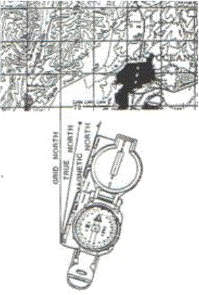
With the map in the
horizontal position, take the straight edge on the left side of the compass and
place it alongside the north-south grid line with the cover of the compass
pointing towards the top of the map. This
will place the fixed black index line of the compass parallel to the north-south
grid line of the map. See Figure 3. c.
Keeping the compass
aligned as directed above, rotate the map and compass together until the
magnetic arrow is below the fixed black index line on the compass.
At this time, the map is close to being oriented. d.
Rotate the map and
compass in the direction of the declination diagram. e.
If the magnetic north
arrow on the map is to the left of the grid north, the compass reading will
equal the GM (grid magnetic) angle given in the declination diagram. The map is now oriented. f.
If the magnetic north
is to the right of the grid north, the compass reading will equal 360 degrees
minus the GM angle. Figure
3. 2.
Second Technique. a.
Determine the
direction of the declination and its value from the declination diagram. b.
Using any north south
grid line on the map as a base, draw a magnetic azimuth equal to the GM angle
given in the declination diagram with the protractor. c.
If the declination is
easterly (right), the drawn line is equal to the value of the GM angle. Align the straight edge, which is on the left side of the
compass, alongside the drawn line on the map.
Rotate the map and compass until the magnetic arrow of the compass is
below the fixed black index line. The
map is now oriented. d.
If the declination is
westerly (left), the drawn line is equal to 360 degrees minus the value of the
GM angle. Align the straight edge,
which is on the left side of the compass, alongside the drawn line on the map.
Rotate the map and compass until the magnetic arrow of the compass is
below the fixed black index line. The
map is now oriented. G.
DETERMINING AN AZIMUTH.
An azimuth is defined as a horizontal angle measured clockwise from a
north base line. This north base
line could be true north, magnetic north, or grid north.
The azimuth is the most common military method of expressing direction.
When using an azimuth, the point from which the azimuth originates is the
center of an imaginary circle. This
circle is divided into 360 degrees. 1.
Magnetic Azimuth.
Determined by using magnetic instruments, such as lensatic compass.
A magnetic azimuth comes from the compass. 2.
Grid Azimuth.
When an azimuth is plotted on a map between point A and point B, the
points are joined together by a straight line.
A protractor is used to measure the angle between grid north and the
drawn line. This measured azimuth
is the grid azimuth. The grid azimuth comes from the map. H.
Converting
Azimuths. As stated
earlier, azimuths measured with a protractor are grid azimuths (measured from
grid north) and azimuths determined with a compass are magnetic azimuths
(measured from magnetic north). Magnetic
azimuths cannot be plotted on a map with a protractor unless they are converted
to grid azimuths and vice versa. 1.
Convert Azimuths Using the LARS
Rule. This can be used to
convert from magnetic to grid or from grid to magnetic. A)
To determine the G-M angle
for the map you are using, perform the following steps: 1)
Go to the declination diagram in the margin of your map. 2)
Place your finger on the north line that corresponds to the azimuth you
have (grid or magnetic). 3)
Move your finger on the north line you are converting to (magnetic or
grid). 4)
Apply the LARS (Left Add,
Right Subtract)
rule. If your finger moved left,
you would add the G-M angle to the beginning azimuth.
If your finger moved right, you would subtract the G-M
angle from the beginning azimuth. I.
LOCATE AN UNKNOWN POINT ON THE
GROUND 1.
Resection.
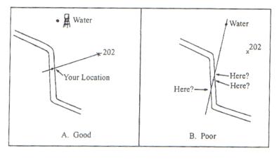
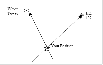
Locating one’s position on the map by determining the grid azimuth to
at least two well-defined locations that can be pinpointed on the map.
For greater accuracy, the desired method of resection will be to use
three well-defined locations. Ensure they are at least 30 degrees apart. a.
Orient the map with compass. b.
Identify two or three known
distant locations on the ground and mark them on the map. c.
Measure the magnetic
azimuth to the known position from your location using a compass.
Figure 4.
d.
Convert the magnetic
azimuth to grid azimuth. e.
Convert the grid
azimuth to a back azimuth. Using a
protractor, scale the back azimuth on the map from known position back to your
known position. f.
Repeat 3, 4, and 5 for a
second position and a third position if desired. g.
Your location is the point
where the lines cross.
Figure
5. 2.
Intersection.
Locating an unknown point by successively occupying at least two known
points on the ground and then map sighting on the unknown location.
It is used to locate distant or inaccessible points or objects such as
enemy targets, danger areas and so forth. a.
Orient the map with compass. b.
Locate and mark your
position on the map. c.
Determine the magnetic
azimuth to the unknown position using the compass. d.
Convert the magnetic
azimuth to grid azimuth. e.
Draw a line on the map
from your position on this grid azimuth. f.
Move to a second known
point and repeat steps 1, 2, 3, 4, 5, and 6.
The location of the unknown position is where the lines cross on the map.
Again, the two positions must be at least 30 degrees apart. J.
PACE COUNT.
Another way to measure ground distance is the pace count.
A pace is equal to one natural step, about 30 inches long.
To accurately use the pace count method, you must know how many paces it
takes to walk 100 meters. To
determine this, you must walk an accurately measured course and count your
number of paces. A pace course can
be as short as 100 meters or as long as 600 meters.
The pace course, regardless of length, must be on similar terrain to what
you will be walking. It does no
good to walk a course on flat terrain and then try to use that pace count on
hilly terrain. To determine your
pace count on a 600-meter course, count the paces it takes to walk the 600
meters, then divide the total paces by six.
The answer will give you the average paces it takes you to walk a 100
meters. It is important that each
person who navigates while dismounted knows his pace count. 1.
Keeping Track of Your Pace
Count. a.
Tie knots on a string. b.
Place pebble in your
pocket for every 100 meters. c.
Place tick mark on a
piece of paper or in a note book. K.
Factors
effectING pace count
1.
Slopes.
Your Pace will lengthen on down slopes and shorten on upgrades. 2.
Winds. A head wind shortens the pace and a tail wind increases it. 3.
Surfaces.
Sand, gravel, mud, snow, will shorten the pace. 4.
Elements.
Snow, rain, or ice will cause pace to shorten. 5.
Clothing.
Excess clothing and boots with poor traction affect the pace length. 6.
Visibility.
Poor visibility, such as fog, rain, or darkness will shorten the pace.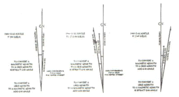
L. STEERING MARKS
1. Steering marks should never be determined from a map study. They are selected as the march progresses and are commonly on or near the highest points along the azimuth line you are following. They may be uniquely shaped trees, rocks, hilltops, posts, towers, buildings, or anything that can be easily identified. If you do not see a good steering mark to the front, you might use a back azimuth to some feature behind you until a good steering mark appears out in front.
2. Dead reckoning without natural steering marks is used when the area through which you are traveling is devoid of features, or when visibility is poor. At night, it may be necessary to send a member of the unit out in front of your position to create your own steering mark in order to proceed. His position should be as far out as possible to reduce the number of chances for error as you move. Hand and arm signals or a radio may be used in placing him on the correct azimuth. After he has been properly located, move forward to his position and repeat the process until some steering marks can be identified or until you reach your objective.
M.
THE
MAP.
1.
Purpose. Permit a person to visualize an area of the earth's surface
with outstanding features properly positioned.
2.
Definition. Reduced, or scale drawing of the ground and important things
on the ground as seen from the air:
a.
Shows us
what an area looks like without actually being there.
b.
A clear
and handy reference tool
3.
Characteristics
of a Map:
a.
Designed
to show us common information.
b.
Location
of ground objects.
c.
Populated
areas.
d.
Routes of
travel.
e.
Communication
lines.
f.
Extent of
vegetation cover.
g.
Elevation
and relief of the earth's surface.
4.
Care
and Importance.
a.
Maps are
printed on paper and require protection from water, mud and tearing.
When you mark on your map, use lighter lines which are easily erased
without smearing. If trimming the
map, be careful not to cut any of the marginal information:
1)
Grid
data.
2)
Magnetic
Declination Data.
3)
Overlapping
Grid Values.
4)
Tick
Marks.
b.
Maps must
be protected because they can hold tactical information such as:
1)
Friendly
positions.
2)
Friendly
supply points.
3)
Patrol
routes with call signs and frequencies.
4)
Control
measures (phase lines).
N.
MAP
ILLUSTRATION.
a.
The
mapmaker uses standard symbols.
b.
They
represent natural and manmade features.
c.
Resemble
as closely as possible, the actual features but as viewed from above.
a.
Black. Used to identify the majority of cultural or man made
features, such as buildings, bridges, and roads not shown in red.
b.
Red. Main roads, built up areas, and special features such as
dangerous or restricted areas.
c.
Blue.
Is for water features; lakes, rivers, swamps, and
streams.
d.
Green. Identifies vegetation such as woods and orchards.
e.
Red
Brown. All landforms: contours, fills, and cuts.
NOTE:
Occasionally other colors may be used to show special information.
These, as a rule, will be indicated in the margin of information. Currently there are changes being made to the color system
which may vary in the margin of information.
O.
MARGIN
& LEGEND INFORMATION.
a.
Located
at the center bottom of the margin, below the map face.
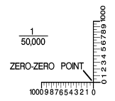
b.
Special
"rulers", ground distance may be measured directly without having to
convert the map scale ratio.
c.
Normally,
the scale for meters, yards, statute miles (land) and nautical miles (sea)
d.
Easy to
use, but notice that "zero" is not at the end of the scale.

Figure
6.
a.
Lay a
straight strip of paper on the map so that the edge touches the center on both
points.
b.
Make a
tick mark on the edge of the paper at each point.
c.
Lay the
paper strip along the scale that corresponds to the unit of measure you are
working with.
d.
Place the
right tick mark of the paper strip on the largest full unit on the primary scale
(to the right of zero), allowing the remainder to fall on the extension of the
scale (to the left of zero).
a.
Make a
tick mark near one end of the irregular line to be measured.
b.
Align the
paper strip along the center of the first straight portion of the line.
c.
Make a
tick mark at the other end of that portion on both the paper strip and the map.
d.
Keeping
both tick marks together, pivot the strip about the second tick mark until
another straight portion of that line is aligned.
e.
Continue
this process until the measurement is completed, then place the paper strip on
the appropriate bar scale and determine the round distance measured.
a.
Located
in the lower left margin.
b.
Illustrates
and identifies some of the symbols on the map.
c.
eVERY TIME a map is used, refer to the Legend to prevent errors in symbol
identification.
a.
A system
of letting us tell someone where specific locations or points are.
b.
A network
of lines, in the form of squares placed on the face of the map.
c.
These
squares are somewhat like the blocks formed by the street system of a city.
d.
The
"streets" in a grid all have very simple names.
The names are all numbers.
e.
Every
tenth line is made heavier in weight. This
will help you find the line you are looking for.
f.
Each grid
line on the map has its own number. These
numbers appear within the map on the line itself.
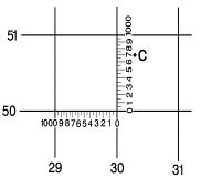
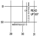
Four digit numbers identify a 1000 square meter grid square.
Six digits identify a 100-meter grid square and eight digits identify a
10-meter grid square.
g.
To locate
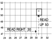
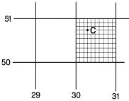
a point by grid reference is a simple matter. We follow a simple rule of map reading: READ RIGHT AND UP.
Locate grid coordinate 303507
on the map in the next figure.
Step #1 |
Step #2 |
Step #3 |
Step #4 |
Step #5 |

Step #6 |
a.
A line
representing an imaginary line on the ground, along which all points are at the
same elevation.
b.
Each
contour line represents an elevation above sea level and the amount of the
contour interval is given in the marginal information.
On most maps, the contour lines are printed brown, starting at zero
elevation, every fifth contour line is a heavier brown line.
These heavy lines are known as index contour lines.
Also, some place along this heavy brown line the elevation is given.
c.
The
spacing lines indicate the nature of the slope. This has important military significance.
d.
Evenly
spaced and far apart indicate a uniform gentle slope.
e.
The
closer the contour lines, the steeper the terrain.
f.
Closely
spaced at the top and widely spaced at the bottom indicate a concave slope.
g.
Widely
spaced at the top and closely at the bottom indicates a convex slope.
h.
In order
to show the relationship of land formations to each other, a map shows a sketch
with different relief features and its characteristic contour pattern.
|
Figure 8. Hill
Figure 9. Draw
Figure 10. Depression
|
REFERENCE
Land Navigation, FM 21-26
Field Medical Service School
Camp Pendleton, California